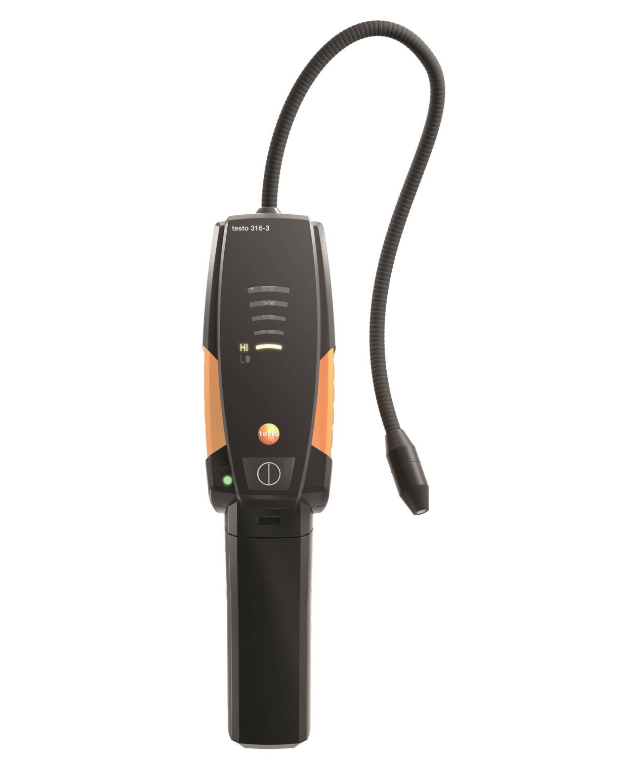
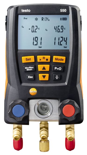
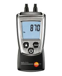
Testo 312-3 - Refrigerant gas leak detector
Special Price 49162
Regular Price: 50919.00
Overview
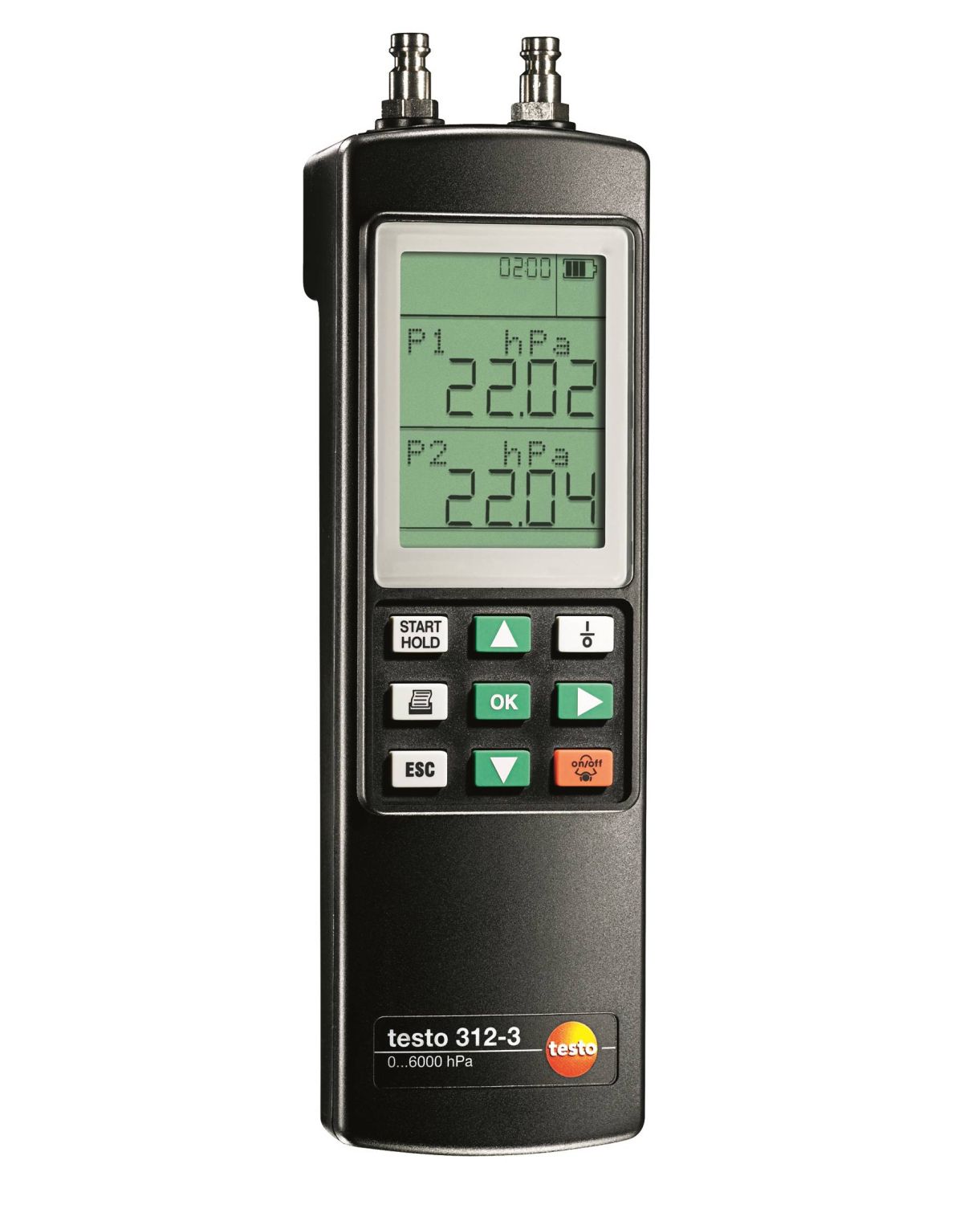
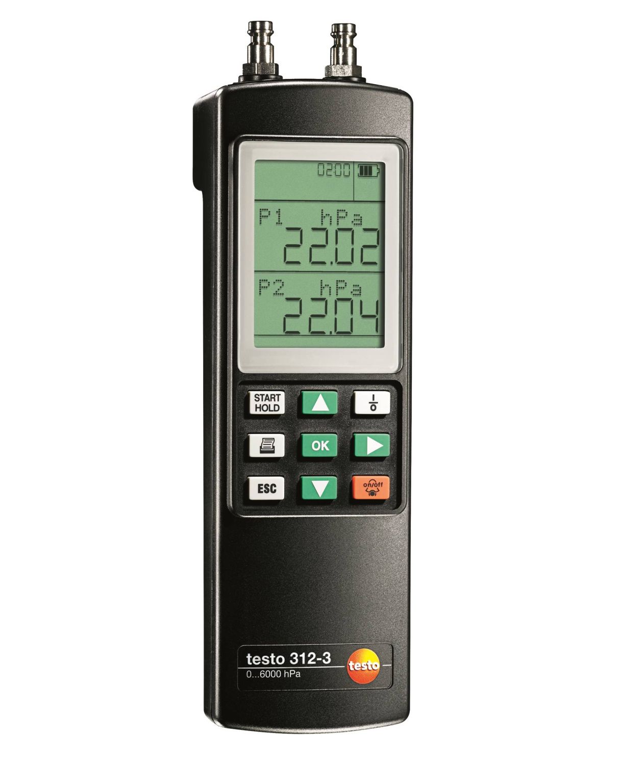
The testo 312-3 Refrigerant gas leak detector is your reliable partner when you want to test water or gas pipes. You can carry out load and tightness tests of gas pipes as well as pressure tests of water pipes using air with the testo 312-3 refrigerant gas leak detector.
- Load and tightness tests of gas pipes
- Pressure testing of water pipes using air
- Switchable measuring ranges with high resolution
- Alarm indicator for undershooting of freely adjustable limit values
Product Description
Before water and gas pipes are commissioned, they should be checked for tightness. You have to carry out a load test in addition to a tightness test on gas pipes. In both cases, pressure is built up in the pipe using air or inert gas and measured over a defined period of time. You can use the testo 312-3 refrigerant gas leak detector for this measurement.
It can also be used for tightness and load tests on water pipes, provided that the pressure test is carried out using air. The testo 312-3 DVGW-tested refrigerant gas leak detector is also useful for other individual pressure measurements.
Testo's reliable testo 312-3 refrigerant gas leak detector measures up to 6,000 hPa. You have the possibility of setting freely adjustable limit values, so that the refrigerant gas leak detector warns you immediately if these limit values are breached by displaying an alarm.
Practical features of the Testo refrigerant gas leak detector
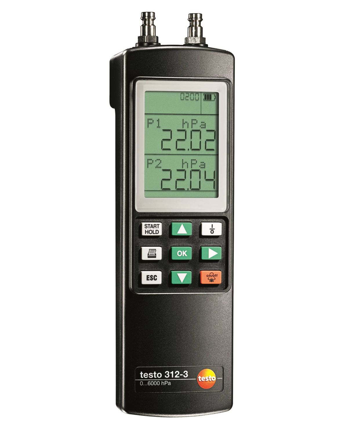
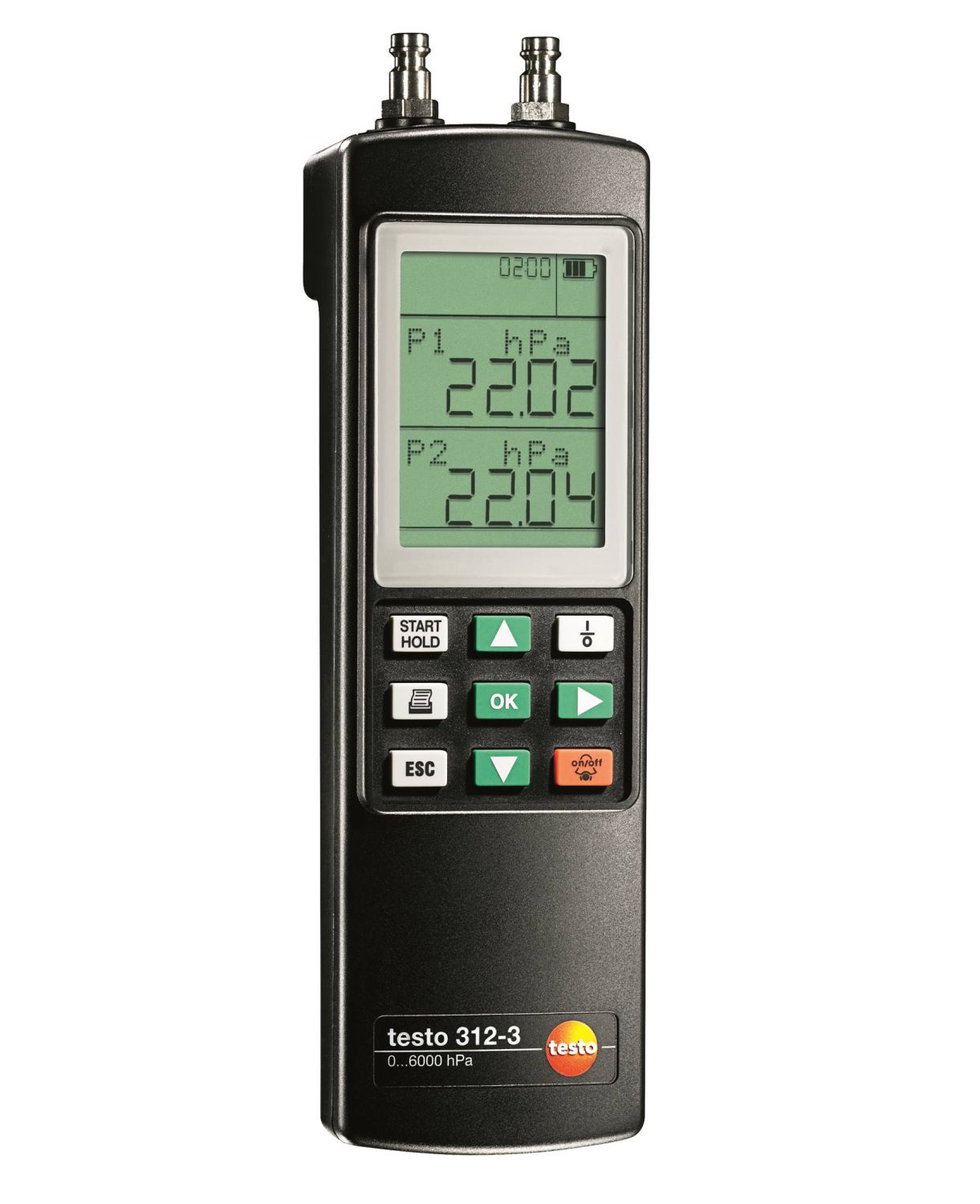
The testo 312-3 refrigerant gas leak detector offers a high level of operating convenience in order for you to carry out pressure measurement efficiently. As well as the measuring values, you can also read the time on the clear display. The measuring ranges are switchable. And the optional testo fast printer means you can produce measurement data printouts directly on site.
Delivery Scope
testo 312-3 refrigerant gas leak detector, including battery and calibration protocol.
| Pressure measurement | |
|---|---|
| Measuring range | -300 to 300 hPa -6000 to 6000 hPa |
| Accuracy | ±0.5 hPa (0 to +50.0 hPa) ±1.5 % of mv (> 50 hPa) ±4 hPa (0 to +400 hPa) ±2 % of mv (+400 to +2000 hPa) ±4 % of mv (+2000 to +6000 hPa) |
| Resolution | 1 hPa (-6000 to +6000 hPa) 0.1 hPa (-300 to +300 hPa) |
| Overload rel. (low pressure) | ±8000 hPa |
| General technical data | |
|---|---|
| Dimensions | 215 x 68 x 47 mm |
| Operating temperature | +5 to +45 °C |
| Housing | ABS |
| Warranty | 2 years |
| Alarmsignal | audible; Optical |
| Alarm untere Grenze | -0.04 hPa |
| Alarm upper threshold | 100 hPa |
| Battery type | 9V block battery |
| Display type | LCD |
| Display size | 2 lines |
| Storage temperature | -20 to +60 °C |
| Weight | 300 g |
Pressure measurements on burners
Checking the gas pressure on burners is one of the standard measurements during services of domestic heating systems. This involves measuring the gas flow pressure and gas resting pressure of the system. The flow pressure, also called supplied pressure, refers to the gas pressure of the flowing gas and resting pressure of the static gas. If the flow pressure for gas boilers is slightly outside the 18 to 25 mbar range, adjustments must not be made and the appliance must not be put into operation. If the burner is nevertheless put into operation, it will not be able to function properly and, when the flame is generated, small explosions will occur and ultimately malfunctions; the burner will therefore shut down and the heating system will fail.
Pressure tests on water pipes
According to the legal regulations of DIN EN 806-4, DIN 1988-7 and DIN 1610, drinking and waste water pipes are to be tested for leaks before being put into service by means of a pressure test with air, inert gas or water; they are also to undergo load testing with air or inert gas. However, for reasons of hygiene, it is best if the pipes remain dry until shortly before commissioning and do not undergo a leak test using water. A pressure test with air is also recommended to prevent metallic materials from corroding. The pressure test is split into two pressure-related parts where test pressure and time depend on the objective (load or leak). Leaks can usually be heard very quickly. If it is difficult to locate the leaks, the usual auxiliary tools and materials for gas pipes are used (spraying or brushing on foaming solutions).
Pressure tests on gas pipes (leak, load test)
The technical regulation for gas installations (in short: TRGI) is a binding and at the same time important regulation for skilled tradespeople. The TRGI governs how gas installations are to be planned, designed, serviced and maintained. This applies to all gas installations. This regulation is taken care of by the German Association for Gas and Water (DVGW). The TRGI 2008 is the current version. Amongst other things, this states that gas pipes are to be tested according to the construction phase (basic shell, completion and repairs). The following checks in particular play a role in the application stated here:
Load test
In this process, the material is tested for stability and the connections for service life; this takes place prior to plastering over or concealment of the gas pipes. During load testing, the newly installed pipe, without fittings or gas appliances, is subjected to 1 bar pressure. The testing medium is air or inert gas. There must be no pressure drop detected during the test, which lasts at least 10 minutes.
Leak test
This test is for checking the pipe for leaks, with fittings and without gas appliances. The measuring instrument must not register any drop in pressure during the minimum 10-minute testing period (depending on the system volume); the test pressure is 150 mbar (previously 110 mbar).
Temperature measurements on radiators
When measuring temperatures on radiators, the flow and return temperature are recorded in particular and assessed by the tradespeople. The flow temperature is defined as the temperature of the thermal transfer medium (e.g. water) that the system is supplied with. The temperature of the medium flowing out of the system is correspondingly called the return temperature. To prevent losses within the heat distribution system and achieve a better level of efficiency, spot recording of flow and return temperatures is necessary. Implementation of relevant measures ultimately leads to hydraulic adjustment on the basis of knowledge about the flow and return temperatures. This defines a procedure with which every radiator or heating circuit of a flat radiator within a heating system is supplied at a set flow temperature with the precise amount of heat needed to achieve the ambient temperature required for the individual rooms. Flawed operating conditions will result in considerable excess consumption of electricity and heating energy. The German Energy Saving Regulation (EnEV) requires hydraulic adjustment for systems being set up or overhauled for this very reason.
Product DataSheets


